
Views: 0 Author: Site Editor Publish Time: 2026-11-21 Origin: Site
Damping factor is a division problem: load impedance divided by the amplifier's output impedance. Nothing more, nothing mystical.
What it physically controls is back-EMF: after the signal stops, the moving cone turns the voice coil into a generator; a low-impedance path brakes the cone, a high one lets it ring.
Solid-state amplifiers routinely deliver 100 or more at the terminals; the real problem zone sits below 20.
Speaker cable and crossover resistance are the hidden denominator: five meters of 14 AWG round trip adds about 0.08 Ω, and a passive woofer inductor adds 0.2–0.6 Ω on top — so real systems land near 10–30.
Beyond roughly 50, differences are inaudible in any practical system. Ask how the number was measured and how stability was tested, not how large it is.
Damping factor describes how firmly an amplifier brakes the loudspeaker cone's overshoot, and it equals load impedance divided by output impedance. Solid-state amplifiers reach 100 and beyond without effort; what actually determines tight bass is the resistance of speaker cable and passive crossovers — and once the system total passes about 20, a bigger number makes no audible difference.
The definition carries no mystery: divide the load impedance by the amplifier's output impedance. An 8 Ω speaker on an amplifier with 0.02 Ω of output impedance gives a damping factor of 400. The figure describes the "stiffness" of the voltage at the amplifier's output terminals — the lower that impedance, the more completely the cone's own generated voltage gets shorted out, and the faster the cone stops. Halve the output impedance and the number doubles:
Amplifier output impedance | Damping factor (8 Ω load) | Where this sits in practice |
|---|---|---|
0.01 Ω | 800 | Achievable in strong designs (and a favorite of spec-sheet inflation) |
0.02 Ω | 400 | Mature Class AB territory |
0.04 Ω | 200 | Common solid-state range |
0.08 Ω | 100 | Comfortably above the floor |
0.40 Ω | 20 | Edge of the problem zone |
2.00 Ω | 4 | Typical tube-amp territory |
Industry-typical magnitudes; exact values depend on feedback depth and output-stage devices.
A solid-state amplifier's output impedance comes from the conduction resistance of its output devices, sense resistors and wiring — typically 0.01–0.05 Ω. It is set by component parameters and feedback depth, which means it can be measured, reproduced, and explained by the factory that built it.

Typical multichannel amplifier chassis (illustrative only)
A woofer plays two roles at once. Driven by the signal, it is a loudspeaker; carried by its own inertia after the signal stops, it is a generator. The still-moving voice coil cuts through the magnetic field and produces a voltage — back-EMF. If that voltage has nowhere to go, the cone coasts on its own momentum: bloated bass, trailing overhang, a one-note "boom" that outlives the note itself. That is what underdamping sounds like. The lower the amplifier's output impedance, the shorter the discharge path, the faster the brake.
One fairness note belongs here: the amplifier is only half of the braking system. The suspension — spider and surround — provides mechanical damping, while the voice coil's own DC resistance and the amplifier's output impedance together form the electrical half. Engineers quantify the mix with Qms (mechanical), Qes (electrical) and Qts (total quality factor), and when a cabinet is tuned, its designer is choosing a point between "underdamped and fat" and "overdamped and dry." The amplifier's damping factor is an external condition of the electrical half only; the other half lives in the driver and the box.
Damping factor is a division, and the denominator is everything between the amplifier's output terminals and the voice coil. Speaker cable sits directly in that path, and its resistance usually exceeds the amplifier's output impedance by an order of magnitude:
Element in the loop | Typical resistance | Damping contribution alone (8 Ω load) |
|---|---|---|
Solid-state amplifier output impedance | 0.01–0.05 Ω | 160–800 |
14 AWG speaker cable (~2.1 mm²), 5 m round trip | ≈0.08 Ω | ≈100 |
16 AWG speaker cable (~1.3 mm²), 5 m round trip | ≈0.13 Ω | ≈60 |
Amplifier + 14 AWG/5 m combined | ≈0.10 Ω | ≈80 |
Wire resistances follow AWG standard resistivity; length counted as a 5 m run, there and back.
The arithmetic is blunt: five meters of ordinary 14 AWG adds four times more resistance than a 0.02 Ω amplifier output. The system's real damping factor divides 8 Ω by the series total of amplifier, cable and crossover — so quoting 400 from the spec sheet while ignoring the wire is a number with no physical meaning.
In a passive home-audio speaker, a low-pass inductor sits between the terminals and the woofer. Its DC resistance typically falls between 0.2 and 0.6 Ω — again, an order of magnitude above the amplifier's output impedance:
Element in the loop | Typical DC resistance | Cumulative damping (8 Ω load) |
|---|---|---|
Woofer low-pass inductor DCR | 0.2–0.6 Ω | 13–40 |
Inductor + 14 AWG/5 m cable | 0.3–0.7 Ω | 11–27 |
Inductor + cable + amplifier (0.02 Ω) | 0.32–0.72 Ω | ≈11–25 |
Series the whole chain and a spec-sheet 400 lands at a system damping factor of roughly 10–30 into a passive speaker. This is why experienced system tuners care about wire gauge, run length and inductor DCR rather than the trailing digits of an amplifier's damping spec.
Put the ranges and audibility side by side and the answer settles:
System damping factor | What actually happens | Audibility |
|---|---|---|
Below 5 | Cone braking visibly slows; bass turns loose and one-note | Clearly audible |
5–20 | Depends on the driver's Qts and the cabinet alignment | Possibly audible, system-dependent |
20–50 | Cable and crossover dominate; amplifier differences dilute | Inaudible in most systems |
50–200 | The cable has already decided | Essentially inaudible |
Above 200 | No physical difference remains | Inaudible |
Audibility framing reflects general industry knowledge; rooms, cabinets and program material all shift the picture.
The working consensus: below 20 is a genuine problem zone, below 5 is plainly audible sloppiness, between 20 and 50 nearly all systems stop telling the difference, and past 50 the spec-sheet figure is marketing material. That is also why some brands print "1000+" — a number that corresponds to 0.008 Ω of output impedance and is buried under cable resistance long before it reaches the voice coil.
Damping problems come in two opposite shapes, and a buyer should recognize both:
Condition | Mechanism | Sonic signature | Typical sources |
|---|---|---|---|
Underdamped | Insufficient electrical damping; the cone overshoots as back-EMF feeds back | Fat bass, overhang, one-note boom | High output impedance designs, very long thin cable, tube amps on insensitive speakers |
Overdamped | Electrical braking too strong; bass starts and stops too abruptly | Tight, dry, lean bass | High-damping solid-state amps on high-Qts alignments (uncommon) |
Damping–cabinet mismatch | The Qts alignment assumed one electrical damping condition and got another | Whole low-frequency balance shifted | Cabinet tuned for one amplifier class, paired with another |
The first row is the real procurement risk. The third is the reminder that damping is a matching problem, not a maximum-spec contest.
Output architecture sets the baseline before any cable is attached:
Architecture | Typical output impedance | Damping factor (8 Ω) | What decides it |
|---|---|---|---|
Class AB solid-state | 0.01–0.05 Ω | 160–800 | Feedback depth, output-device conduction resistance |
Class D solid-state | 0.02–0.10 Ω | 80–400 | Output LC filter, feedback scheme (mixed voltage/current feedback does better) |
Tube (output transformer) | 0.4–4 Ω | 2–20 | Transformer windings, tube plate resistance, feedback amount |
Industry-typical magnitudes.
Class AB amplifiers reach 0.02 Ω through mature, well-understood practice. Class D adds an output LC filter whose impedance varies across the audio band, and the speaker's own impedance curve modulates the response and low-frequency damping in return — which makes Class D damping performance a direct function of the feedback architecture. Designs using mixed voltage and current feedback pull the effective output impedance down to Class AB levels, and that single question — what feedback scheme does this design use — separates serious Class D engineering from the rest. Tube amplifiers sit where the output transformer puts them: 2–20 is physics, not neglect, and it explains the systematic difference in bass character between tube and high-damping solid-state systems.
Output impedance is measurable and reproducible, and factory practice is straightforward:
What is checked | How (standard factory practice) | Record and criteria |
|---|---|---|
Output impedance | Loaded/unloaded voltage-difference method: measure output voltage into open circuit and into a 4 Ω/8 Ω dummy load at the same signal, derive impedance from the sag | Derived value and test conditions on file |
Damping factor rating | Stated at 1 kHz into rated load, with conditions printed | Spec sheet matches the test record |
Low-frequency stability | Stability testing into dummy and capacitive loads, per unit | Per-unit test records |
Bass control by ear | Standardized low-frequency test signals at listening check | Listening records |
Any damping number on a spec sheet should trace back to a record with test conditions. A number that cannot be measured back, or a supplier who cannot describe the method, is not a specification — it is decoration.
Damping factor is one of the highest-information questions to put to a supplier, because the answer exposes design, measurement and test discipline at once:
Ask | Evidence to request | Answers that should worry you |
|---|---|---|
How is damping factor / output impedance measured | Method and conditions: load, frequency, instrument | A big number with no method behind it |
How is low-frequency stability verified | Per-unit stability records into dummy and capacitive loads | No stability test item at all |
What feedback scheme does the Class D line use | Design rationale or verification report | Cannot explain what the output filter does |
What load and cable guidance do you publish | Load-matching and wire-gauge recommendations in the manual | No guidance on load matching |
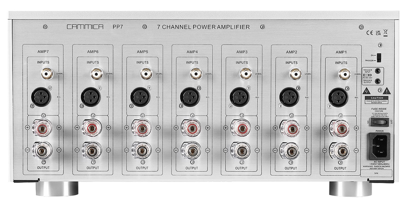
Typical rear panel speaker terminals (illustrative only)
Three boundaries keep damping factor a real engineering topic instead of a mystical one. In active subwoofers and powered speakers the amplifier lives inside the cabinet, the loop shortens to centimeters, and low-frequency control is decided by limiters, DSP and cabinet alignment — swapping in a "higher-damping" external amplifier is not an option there. In 70V/100V constant-voltage commercial systems, the loudspeaker side sits behind an impedance-matching transformer, and damping factor effectively exits the conversation. And in long custom-install runs, cable resistance becomes the dominant term — the variable to manage is wire gauge and length, not a hunt for a bigger number. A supplier who knows these boundaries is showing design judgment, not just test records.
"Higher damping factor always sounds better." Past 50 the physical difference is inaudible; system damping is set by cable and crossover resistance, so the amplifier-only figure is marketing material.
"A DF-1000 amplifier makes every speaker tight." Five meters of ordinary wire pulls it back to a few dozen. Bass control is a system property.
"Tube amps always have bad bass." Low damping factor is a fact; matched with a high-Qts alignment and short cable, tube bass is clean. Matching beats the number.
"Class D damping is always worse than Class AB." It depends on the feedback scheme; mixed-feedback Class D designs reach Class AB levels.
"Damping is the amplifier's parameter alone." Electrical damping is half the story; the driver's Qts and the cabinet alignment are the other half.
Q1: Under what conditions is the spec-sheet damping factor measured? Industry practice calibrates at 1 kHz into the rated load (4 Ω or 8 Ω). Reputable suppliers print the conditions; a large number with none attached has limited value.
Q2: My bass booms and trails — is the amplifier's damping at fault? Not necessarily. Room modes, cabinet tuning and placement can all produce it. Swap to a short, heavy-gauge cable first, then to an amplifier known to have lower output impedance; if the overhang disappears, the damping loop was the culprit.
Q3: Why does Class D bass control sometimes feel less settled than Class AB? The LC filter before the Class D output stage has frequency-dependent impedance, and the speaker's impedance curve feeds back into response and damping. Mixed voltage/current feedback designs suppress this to Class AB levels — worth asking the supplier directly.
Q4: How do you protect bass control in long custom-install runs? Increase gauge, shorten runs. As industry practice, runs longer than 10 m one-way call for 14 AWG or heavier cable — at that length, the cable resistance is already the dominant term in the system's damping.
Typical four-channel amplifier front panel (illustrative only)
Three facts carry the engineering meaning of damping factor. It is a division: load impedance over output impedance. It brakes the cone by shorting the back-EMF that a moving driver generates. And in any real system it is diluted by cable and crossover resistance — solid-state amplifiers deliver 100 or more at the terminals, passive speakers land near 10–30 as systems, and differences above 20 are inaudible. For buyers, three actions follow: move attention from the amplifier's damping number to wire gauge, run length and inductor DCR; ask Class D suppliers about their feedback scheme and output filter; and write the impedance measurement method and stability test records into the factory audit list, so bass control becomes verifiable evidence instead of a claim.
To see the workstations and instruments behind tests like these, start with the workshop and measurement stations documented on our factory page; our series on amplifier design and manufacturing is collected in our engineering notes on amplifier design and manufacturing; and the product lines these damping and load-matching topics apply to are listed in the amplifier and speaker product lines currently in production.


