
Views: 0 Author: Site Editor Publish Time: 2026-11-20 Origin: Site
The power supply, not the output stage, decides how much current an amplifier can deliver instantly — and how much it weighs and whether it hums.
Toroidal transformers trade weight for current reserve: a mains-frequency core is real steel and copper, and the same power from a switching supply weighs an order of magnitude less.
Hum is a layout discipline, not a parts choice. Toroidal hum comes from 50/60 Hz magnetic leakage; SMPS noise from switching leaking into the audio path. Both are solved at PCB and chassis level.
Failure modes barely overlap: capacitors and heat are common enemies; loosening and inrush sit on the linear side, switching devices and EMI on the SMPS side.
You can identify the supply architecture without opening the chassis — weight, standby power, spec-sheet wording and hum behavior are enough.
At equal power, a toroidal supply typically weighs several times more than a switching supply and hums more; the switching supply is lighter and more efficient but must clear two compliance hurdles — EMC and standby power. Neither is simply better; the choice depends on channel count, power class and your market's efficiency rules.
A linear supply follows a short path: mains enters a toroidal transformer that steps the voltage down at 50 or 60 Hz, a bridge rectifier turns it into pulsating DC, and large electrolytic banks store and smooth it for the output stage. The core is a steel ring with both windings laid directly over it. Nothing in the chain is regulated — output voltage tracks the mains within a small band, which is what "linear" means: continuous, analog conversion.
A switching supply takes a different route: mains is rectified to high-voltage DC, chopped by power MOSFETs at hundreds of kilohertz, stepped down through a small high-frequency transformer, then rectified, filtered and regulated. Because the switching frequency is thousands of times the mains frequency, the core needed for the same power shrinks by one to two orders of magnitude — the root of its light weight.
Dimension | Linear (toroidal transformer) | Switching (SMPS) |
|---|---|---|
Voltage conversion | Mains-frequency transformer, 50/60 Hz | High-frequency transformer, tens-to-hundreds of kHz |
Core components | Steel ring core, copper windings, mains rectifier, large electrolytics | EMI filter, MOSFETs, ferrite core, low-voltage rectification |
Output regulation | Unregulated; tracks mains fluctuation | Closed-loop regulated; output holds steady |
Typical full-load efficiency (industry-general) | ~60–85%, noticeable light-load loss | ~85–95%, low light-load loss |
Where the weight lives | Transformer dominates chassis mass | Core shrinks by 1–2 orders of magnitude |
Industry-typical magnitudes; exact values depend on power class and design.

Typical multichannel amplifier chassis (illustrative only)
Transformer volume shrinks as frequency rises: the lower the frequency, the more core cross-section and turns are needed for the same power. A 50 Hz transformer is real silicon steel and copper; a several-hundred-kHz one is a small ferrite core. As an industry-typical magnitude, a mains-frequency transformer can weigh an order of magnitude more than its high-frequency equivalent — the single fact behind the feel of toroidal amplifiers versus light SMPS models.
For buyers, the gap compounds in three directions. Channel count multiplies it: in a seven- or eleven-channel amplifier, each channel adds capacity and storage under a linear scheme. Installation constraints amplify it: commercial work lives on 19-inch racks with load limits, where lightweight SMPS units are easier to specify. And logistics: freight is charged by weight, so across a full container the architecture choice is a real landed-cost line item (industry knowledge, not a quotation). The counterweight: flagship two-channel amplifiers keep the mass deliberately — a large transformer is physical evidence of current reserve, and in that segment heft sells.
Toroidal hum comes from mains-frequency magnetic leakage: even with symmetric windings, the ring core leaks flux, and a 50/60 Hz field induces hum into nearby signal runs, RCA and XLR inputs and any high-gain stage in front. Hearing is brutally sensitive at 100/120 Hz — a few millivolts is audible in a quiet room. Suppression is a layout discipline, not a single component:
Hum source | Mechanism | Verifiable factory countermeasure |
|---|---|---|
Magnetic coupling into signal runs | Mains-frequency field induces voltage | Place transformer away from input stages; rotate for minimum coupling angle |
Mechanical transformer vibration | Incomplete varnish impregnation; loose mounting; mains-harmonics buzz | Vacuum impregnation; torque-specified fastening with records |
Ground loops | Multiple ground points form a loop carrying mains current | Single-point grounding; signal and power grounds separated |
Storage-capacitor ripple | Insufficient or aging capacitance | Capacitance sized to power class; incoming inspection |
An SMPS hums differently — at switching frequency, not mains. Chopping noise leaks into the audio path as high-frequency hiss, controlled by EMI filtering, power/signal partitioning and grounding. The discipline is the same in kind; the battlefield moves from 50 Hz to hundreds of kilohertz. Either way, hum and noise belong in per-unit test records taken in a low-background-noise room — records a buyer can simply ask to see.
Linear supplies lose energy in the transformer's core and copper losses and the drop across rectification. Industry-typical full-load efficiency lands around 60–85%, and light-load behavior is proportionally worse — an energized transformer heats whether or not the amplifier works. Switching supplies lose far less in their semiconductors — typically 85–95% at full load, with much better light-load performance.
Aspect | Linear supply | Switching supply |
|---|---|---|
Full-load efficiency (industry-general) | 60–85% | 85–95% |
Standby / no-load behavior | Transformer heats continuously; standby draw runs high | Can reach the ~0.5 W range to satisfy ErP-type rules |
Thermal load on the chassis | Heat sinks and ventilation sized for a continuous source | Lower heat; more compact enclosures possible |
Long-term energy cost (commercial duty) | Higher | Lower |
Standby power is no longer a bonus in the EU and similar markets — it is a threshold. Efficiency rules set standby limits in the 0.5 W range (industry-general framing; current regulatory text governs). Light load and standby are the natural home ground of a switching supply; a linear design gets there only with a standby relay or an auxiliary low-power rail — extra complexity either way, and a core reason European buyers specify SMPS at a much higher rate.
The central tension in power-supply design is that music is transient: the output stage draws far more than average current within milliseconds. A linear supply answers with storage — large electrolytic banks sit on the output-stage rails, capacitors answer the transient first, the transformer replenishes behind. Bank size and transformer impedance set how deep the voltage sags, which is why flagship linear designs are so large.
A switching supply answers with speed: closed-loop regulation corrects the output within milliseconds, peak current supported by the switching cycle and output capacitance. Regulation is tighter, but peak reserve is whatever the design allocated — not something physically in the chassis. Both routes can be engineered well or badly; the deciders are margin and validation depth, not the label. Measured behavior — power retention into different loads, voltage stability under sustained dynamics — beats any architecture debate.
The failure catalogs barely overlap, which is exactly why the factory test items differ:
Failure mode | Toroidal (linear) | SMPS | Verifiable process behind it |
|---|---|---|---|
Electrolytic capacitor failure | Low-voltage bank dries out, ESR rises | High-voltage bank sits across the full mains; dry-out and bulge risk higher | 105 °C-rated parts with derating; incoming inspection |
Windings and core | Winding insulation aging; thermal protector trips | High-frequency transformer saturation; core overheating | Temperature-rise testing; per-unit protection tests |
Mechanical loosening | Loose toroid mounting produces buzz | Fan wear (where fitted) | Torque-specified fastening with records; vibration testing |
Inrush | Large turn-on surge; needs suppression | Suppressor parts (NTC/relay) fail | Inrush testing; component incoming checks |
Power semiconductors | Rectifier bridge overcurrent | MOSFET overvoltage/overcurrent failure; X/Y capacitor failure | Per-unit protection tests; burn-in screening |
EMI degradation | Largely not applicable | Aging filter parts let emissions drift out of limit | Periodic EMC sampling; production consistency control |
The shared headline: in both architectures, electrolytic capacitors lead the failure list — only the location differs. Linear supplies run their bank on the low-voltage, high-current side; switching supplies run theirs at full mains voltage and higher temperature. Capacitor grade and operating temperature are therefore the shared reliability criteria, and the rule of thumb — capacitor life roughly halves for every 10 °C rise inside the enclosure — applies to both.
Compiled from general industry knowledge; paired processes are standard factory practice.
The two architectures carry different compliance loads. A linear supply's EMC burden is comparatively light — mains harmonics dominate. A switching supply is an intentional noise source: conducted and radiated emissions must be engineered out at the design stage, and the EMI filter, shielding and layout decide whether the unit passes. Buyers can map the evidence demand like this:
Test item | Linear-side focus | SMPS-side focus | Evidence a buyer can request |
|---|---|---|---|
EMC conducted / radiated | Lighter; mains harmonics dominate | The decisive item; filter and shielding design decide | Whole-unit EMC report; certificate holder consistency |
Standby power | Needs auxiliary circuitry to comply | Natural strength | Standby measurement records, per-unit or sampled |
Temperature rise | Transformer and heat sinks are the sources | High-voltage capacitors and switching devices are the sources | Temperature-rise records with defined criteria |
Safety distances / insulation | Transformer insulation class | Creepage around the high-frequency transformer and HV zone | Safety-spec review records |
Turn-on surge | Inrush-limiting design | Suppressor component reliability | Inrush and turn-on test items |
Regulatory specifics follow current market texts; the table reflects engineering practice.
Four external clues, roughly in order of trustworthiness, settle it in ordinary sourcing conversations:
Clue | Toroidal (linear) | Switching (SMPS) |
|---|---|---|
Chassis weight | Distinctly heavy; several times heavier at equal channel count | Light; slim enclosures possible |
Standby power figure | Often several watts, or unlisted | Usually specified below 0.5 W with an efficiency rule cited |
Spec-sheet wording | "toroidal transformer" appears explicitly | "switching power supply" / "regulated output" appears |
Powered hum behavior | Possible mains-frequency hum on silent tracks | No mains hum; poor designs show high-frequency hiss |
Weight is the most honest clue — physics sets it, and marketing cannot dress it up. A stated sub-0.5 W standby figure is the compliance signal: either a switching supply or a hybrid with an auxiliary rail. Cross-check the two and the sourcing conversation starts on solid ground.
Deciding by application beats "which is more modern":
Application | Better fit | Why |
|---|---|---|
Flagship two-channel / home-cinema power amp (Class AB, high power) | Toroidal | Instant current reserve, low impedance; mass itself is part of the quality story |
Seven-plus channel home amplifiers | Either, by power class | At high channel counts the SMPS weight and heat advantage compounds |
Commercial 70/100V distributed audio | SMPS | Efficiency rules, rack load limits, continuous-duty heat |
Wall-mount, slim, custom-install formats | SMPS | Chassis depth and weight are hard constraints |
EU and other strict energy-regulation markets | SMPS mainly | Standby threshold is hard for a bare linear design to clear |
Brands building a "built to outlast" narrative | Toroidal | Simpler structure, serviceability, long-lived mains-frequency parts |
The last row is engineering fact, not marketing convenience: a toroidal supply is structurally simple with few failure modes, so longevity is easy to design in — but a factory that derates and hardens a switching supply properly builds a long-life SMPS just the same. Architecture defines the easier path, never the outcome.
Power-supply architecture is one of the highest-information directions to question in a factory audit, pulling design, process and test capability into one conversation:
Ask | Evidence to request | Answers that should worry you |
|---|---|---|
What drives the architecture choice per product line | Architecture rationale and design-margin documents by line | "We follow industry practice" — no information |
How hum and noise are tested | Per-unit test records in a low-background-noise room, with pass limits | "We just listen" with no records |
How temperature rise is measured and judged | Test points, duration and defined pass criteria | No fixed criteria; ad-hoc hand checks |
EMC report and certificate holder | Whole-unit EMC report; holder's relationship to the factory | Certificate holder does not match the actual plant |
Capacitor selection and derating rules | Capacitor datasheets and derating policy | Cannot state temperature grade or derating ratio |
How standby compliance is ensured | Standby measurements (per-unit or sampled) | Cites the regulation but shows no own data |
Take this table straight into the audit checklist: every row corresponds to a document or work station that either exists or does not — a gap more honest than any brochure.
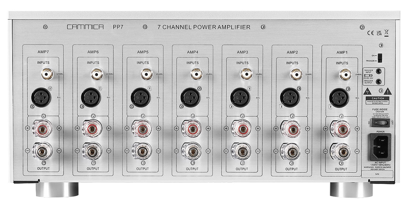
Typical rear panel with AC inlet and fuse holder
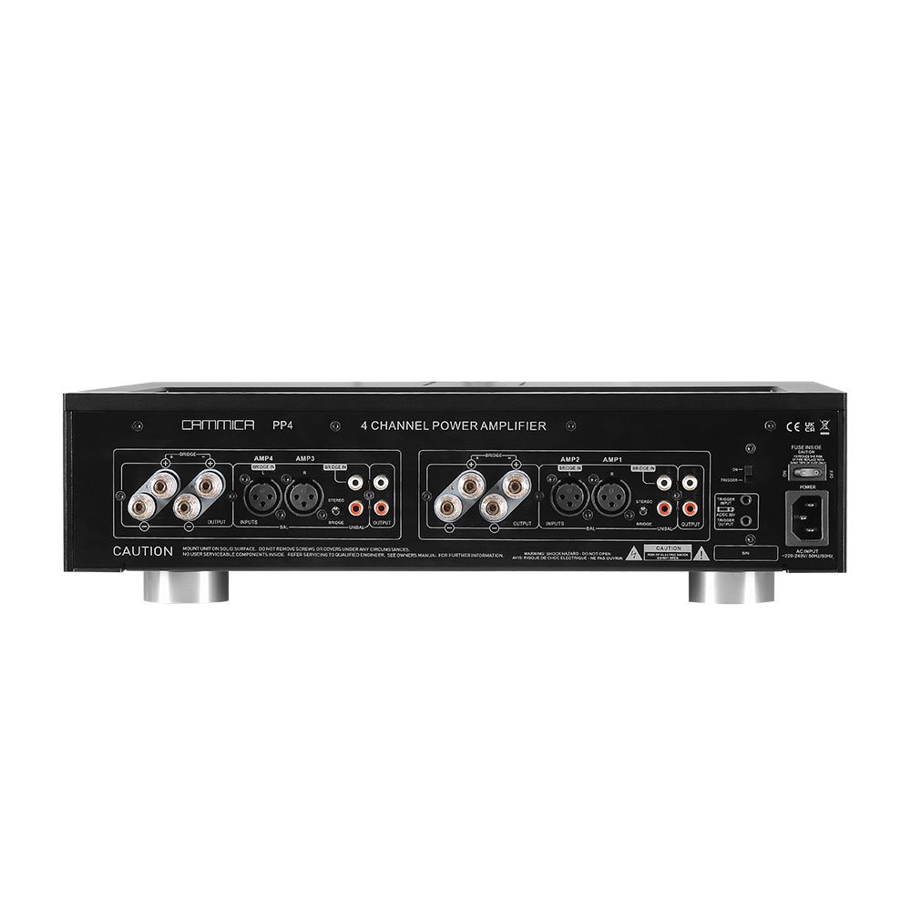
Typical four-channel amplifier front panel (illustrative only)
"Heavy means good." Weight evidences current reserve, but only within the same power class; a 500 W toroidal chassis against a 300 W SMPS chassis tells you nothing.
"Switching supplies always sound worse." 1990s residue: a well-designed modern audio SMPS matches linear designs on noise, dynamics and stability; the gap comes from design quality, not the label.
"Toroidal designs need no EMC discipline." Mains-frequency fields are interference too — hum control is that discipline, just at a different frequency.
"Higher efficiency means SMPS is always the right pick." Efficiency is a constraint, not the objective; a flagship amplifier prioritizes current reserve over electricity cost.
"Standby watts are a rounding error." In regulated markets it is an entry threshold; in operation it is energy billed year after year.
Q1: Is slight mechanical hum from a toroidal amplifier normal? A faint mechanical buzz at no-load, heard up close, is common; at normal listening distance it should be inaudible. Audible hum points to layout or assembly problems — ask for the factory's hum test records.
Q2: Do SMPS amplifiers fail sooner under sustained full load? Reliability tracks derating and thermal control, not architecture. High-voltage capacitor grade and switching-device temperature rise decide the outcome; temperature-rise records and capacitor specifications are the most direct audit evidence.
Q3: Is it normal for one brand to use both architectures? Normal and widespread: splitting by product line — linear for flagships, SMPS for multichannel and commercial lines — is established practice.
Q4: What does a 230 V / 120 V version change for each architecture? A toroid is wound for the target mains or switched via dual primaries; SMPS designs are typically wide-input, so adaptation costs less — for export lines, SMPS wins on flexibility.
The debate is a contest between two routes: physical storage versus high-frequency conversion. The first buys instant current reserve with steel and copper, paying in weight, hum discipline and standby draw; the second buys efficiency, light weight and tight regulation, paying in EMI engineering and compliance thresholds. Their failure catalogs barely overlap — capacitors and heat are shared enemies; loosening and inrush lean linear-side, switching devices and EMI drift lean SMPS-side. For buyers, three actions: choose by application — current reserve favors toroidal, while light weight, many channels and strict energy rules favor SMPS; cross-check architecture from weight, standby figure and hum behavior; and write hum, temperature-rise, EMC and standby records into the audit checklist so capability becomes evidence rather than a claim.
To see what these test items look like as real stations on a production floor, start with our production-line photos and per-unit test equipment archive; the wider series on amplifier engineering and sourcing decisions is collected in our engineering and manufacturing knowledge column; and the product ranges these architectures cover are listed in the amplifiers and speakers currently in production.


